VibroLaserScanSet

VibroLaserScanSet
Scanning Laser Doppler Vibrometer
The laser beam of the Scanning Laser Doppler Vibrometer is deflected by two mirrors which are controlled by a computer. A built-in camera delivers the picture of the object under test. On this picture, the measurement points can be arranged with CAD software. After the initial setup of the points, the measurement is done automatically by the computer. Nearly all components of a conventional Scanning Laser Vibrometer are built in a optical unit that is structurally complex and therefore expensive.
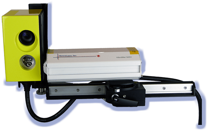
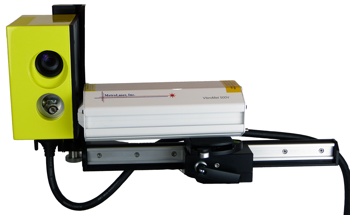
The Vibrolaser ScanSet now overcomes this restrictions and delivers a very high level of performance in measuring. And it simply upgrades an existing single-point laser vibrometer to a fully equipped scanning laser vibrometer system. Simply fix your existing Laser Vibrometer (or a new one by your choice) with the quick release clamps, adjust the mirror unit by the linear slides, and you are ready for the measurement. The VibroLaser ScanSet is shipped with a Data Acquisition with 4 analog input channels to measure the laser and reference signals. The user-friendly measurement and analysis software quickly processes the vibrations data, graphical display, and animations.
VibroLaser Scanset Components:
- ScanSet with mirrors, camera and support for the SinglePoint Laser.
- Controller including 4 channel data acquisition.
- Control and Analysis Software.
- Single point Laser Doppler Vibrometer (optional).
The VibroLaser ScanSet is manufactured from robust aluminium, and has next to the high precision laser deflection unit a CCD-Camera for photo realistic capture of the measurement object. To ensure that the laser beam of any usual Laser-Vibro meter exactly hits the mirror axis in zero position, the VibroLaser ScanSet offers linear slides that can be easily fixed by clamping lever to en sure a precise and reliable laser positioning. Using a ScanSet for measuring the signal quality is only dependant on the specifications and quality of the used Laser Doppler Vibrometer. The electrical connection to the controller is simply realized by a single cable that also supplies the mirrors with power, takes care about the mirror and camera steering and carries the measurement data and CD-Camera Signals.
The controller includes next to the power supplies, an electrical component to steer the mirrors an a data acquisition system to digitize the vibration signals. The controller has a direct connector for the central cable to the ScanSet, BNC connectors for the input channels and the generator output and one USB connector to communicate with measurement PC. The Notebook/PC is only connected with one USB-cable for mirror and CCD-Camera steering, vibration data an video stream.
Data Acquisition:
| Channels: | 4 synchronous analogue input channels |
| A/D converter: | 24 Bit resolution |
| Frequency ranges: | 1 to 20.000 Hz selectable in 1, 2, 5, 10 steps |
| Frequeny resolution: | max. 25.600 Frequeny lines |
| Input ranges: | ±1 V or ±10 V selectable |
| Coupling: | AC, DC, ICP Supply (2...4 mA) |
| Anti-Aliasing Filter: | Delta Sigma, adjusted to frequency range |
| Generator output: | Sine, Chirp, Noise and Step-sine |
The measurement and analysis software includes all necessary modules to do complete scanning jobs such as:
- CCD-Picture capture, Live Display
- Geometry and Measurement Point Editor
- FFT Analyzer with extensive functionality
- Mirror control and steering
- Operation Deflection shapes (ODS)
- Animation, AVI-Export,UFF– , ASCII– and MatLab- Export
- Free Offline-Version to use in office
- Modal analysis module optional
- Operation system Windows7


